The GHK (G-Hook) was the first fastener design I attempted to make for a backpack using a 3D printer. It quickly became apparent that 3D-printed g-hooks, even for 1” webbing, weren’t rigid enough for real world use. There are mass-produced, injectio
       
     
 I tried increasing rigidity by using a more sophisticated 3D printing technology (CFF - Continuous Filament Fabrication), which uses continuous strands of either carbon fiber or glass fiber to reinforce a nylon-carbon fiber composite material. Altho
       
     
 Fusion 360 has a great built-in CAM engine that allows me to easily go from CAD modeling to tool path creation for CNC machining. I saw a great opportunity to simultaneously learn Fusion’s CAM features and create a much stronger, metal version of th
       
     
 This project starts with a 2” x 2” piece of 6061-T6 aluminum that is cut and machined to size from bar stock.
       
     
 The stock gets mounted in a pair of soft jaws and positioned against a vice stop.
       
     
 The first operation does most of the machining work, including the entire profile, webbing pocket, pocket groove, and engraving.
       
     
 First operation completed.
       
     
 For the second operation, the part gets flipped over and remounted against the stop. The dial indicator shown here is used for measuring part deflection upwards as a result of clamping pressure; this allows successive parts to be mounted with a cons
       
     
 In this operation, the g-hook gets machined to its final thickness, the pocket gets finished, and any remaining sharp edges are broken.
       
     
 Front of the finished part.
       
     
 Paint does’t stick to a machined aluminum surface very well, so the g-hooks are media blasted and washed to remove any machining imperfections, contamination from the machining process, and to increase the surface roughness.
       
     
 Front of the media blasted part.
       
     
 After the g-hooks are media blasted, they are painted and laser engraved to achieve the final look. Powder coating would have given a more durable finish, but it requires specialized equipment and a dedicated oven for curing. I also considered hard
       
     
 The first “finished” version of the g-hook had a 3D printed slider made from Taulman Bridge (Nylon 6). Given the size and geometry of the slider, it didn't make sense to machine this part, though 3D printing with nylon isn’t exactly easy. The hygros
       
     
 I wasn’t satisfied with the first run of laser markings shown here on the initial prototype. The first laser engravings were done too fast with too much power and on paint that had not cured fully.
       
     
 The finished body of the GHK-MK9.
       
     
 With some additional testing on sample material, I was able to get better resolution and contrast by dramatically reducing both engraving speed and laser power.
       
     
 The finished body of the GHK-MK10, a prototype with a non-adjustable center bar. This version is quicker to machine, but the webbing in non-adjustable g-hooks tends to come loose much easier.
       
     
 Rear shot of the finished GHK-MK10 prototype.
       
     
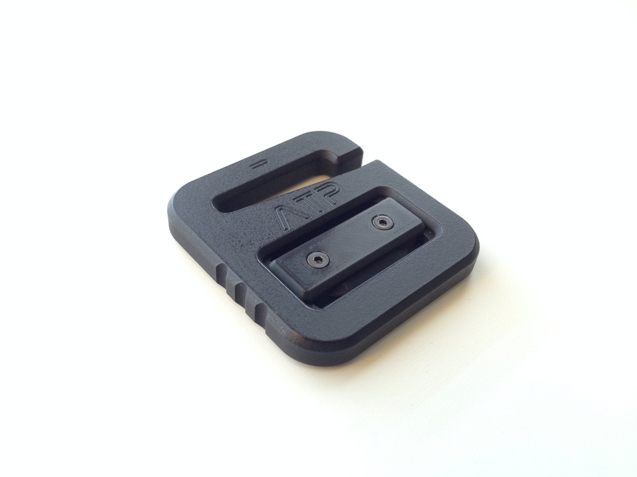
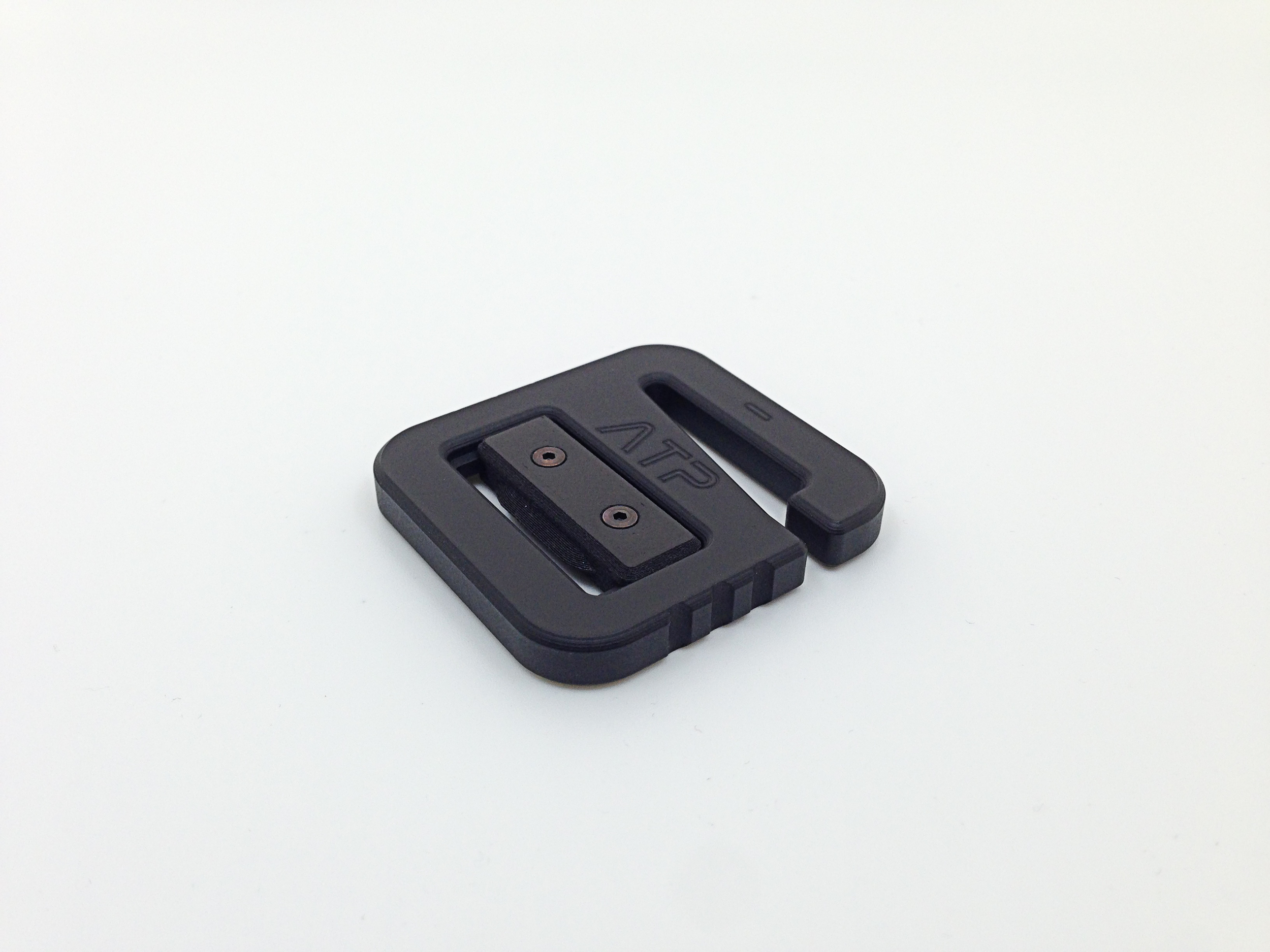
 An assembled GHK-MK9 prototype. The final version has a slider printed from a nylon-carbon fiber composite, as opposed to Nylon 6, which is a closer match to the paint on the body. The composite slider also tends to bind less in the recess.
       
     
 Rear shot of the finished GHK-MK9 prototype.
       
     
 The GHK (G-Hook) was the first fastener design I attempted to make for a backpack using a 3D printer. It quickly became apparent that 3D-printed g-hooks, even for 1” webbing, weren’t rigid enough for real world use. There are mass-produced, injectio


The GHK (G-Hook) was the first fastener design I attempted to make for a backpack using a 3D printer. It quickly became apparent that 3D-printed g-hooks, even for 1” webbing, weren’t rigid enough for real world use. There are mass-produced, injection molded versions made from acetal or GFN that appear to work well, but these can sometimes be difficult to procure and/or expensive when purchased individually. 3D printing with acetal, GFN, and even polycarbonate is possible, but can be challenging given the harmful fumes and higher extrusion/build chamber temperatures required.

 I tried increasing rigidity by using a more sophisticated 3D printing technology (CFF - Continuous Filament Fabrication), which uses continuous strands of either carbon fiber or glass fiber to reinforce a nylon-carbon fiber composite material. Altho


I tried increasing rigidity by using a more sophisticated 3D printing technology (CFF - Continuous Filament Fabrication), which uses continuous strands of either carbon fiber or glass fiber to reinforce a nylon-carbon fiber composite material. Although the final part was stronger and more rigid, these prototypes proved to be more expensive to make, printed less reliably, and took far longer to manufacture than non-CFF versions. Pictured here is an early 1.5” version of the GHK using continuous strands of fiberglass for reinforcement.

 Fusion 360 has a great built-in CAM engine that allows me to easily go from CAD modeling to tool path creation for CNC machining. I saw a great opportunity to simultaneously learn Fusion’s CAM features and create a much stronger, metal version of th


Fusion 360 has a great built-in CAM engine that allows me to easily go from CAD modeling to tool path creation for CNC machining. I saw a great opportunity to simultaneously learn Fusion’s CAM features and create a much stronger, metal version of the GHK.

 This project starts with a 2” x 2” piece of 6061-T6 aluminum that is cut and machined to size from bar stock.


This project starts with a 2” x 2” piece of 6061-T6 aluminum that is cut and machined to size from bar stock.

 The stock gets mounted in a pair of soft jaws and positioned against a vice stop.


The stock gets mounted in a pair of soft jaws and positioned against a vice stop.

 The first operation does most of the machining work, including the entire profile, webbing pocket, pocket groove, and engraving.


The first operation does most of the machining work, including the entire profile, webbing pocket, pocket groove, and engraving.

 First operation completed.


First operation completed.

 For the second operation, the part gets flipped over and remounted against the stop. The dial indicator shown here is used for measuring part deflection upwards as a result of clamping pressure; this allows successive parts to be mounted with a cons


For the second operation, the part gets flipped over and remounted against the stop. The dial indicator shown here is used for measuring part deflection upwards as a result of clamping pressure; this allows successive parts to be mounted with a consistent force.

 In this operation, the g-hook gets machined to its final thickness, the pocket gets finished, and any remaining sharp edges are broken.


In this operation, the g-hook gets machined to its final thickness, the pocket gets finished, and any remaining sharp edges are broken.

 Front of the finished part.


Front of the finished part.

 Paint does’t stick to a machined aluminum surface very well, so the g-hooks are media blasted and washed to remove any machining imperfections, contamination from the machining process, and to increase the surface roughness.


Paint does’t stick to a machined aluminum surface very well, so the g-hooks are media blasted and washed to remove any machining imperfections, contamination from the machining process, and to increase the surface roughness.

 Front of the media blasted part.


Front of the media blasted part.

 After the g-hooks are media blasted, they are painted and laser engraved to achieve the final look. Powder coating would have given a more durable finish, but it requires specialized equipment and a dedicated oven for curing. I also considered hard


After the g-hooks are media blasted, they are painted and laser engraved to achieve the final look. Powder coating would have given a more durable finish, but it requires specialized equipment and a dedicated oven for curing. I also considered hard anodizing these parts, but the batch fee for such a small number of prototypes was too high.

 The first “finished” version of the g-hook had a 3D printed slider made from Taulman Bridge (Nylon 6). Given the size and geometry of the slider, it didn't make sense to machine this part, though 3D printing with nylon isn’t exactly easy. The hygros


The first “finished” version of the g-hook had a 3D printed slider made from Taulman Bridge (Nylon 6). Given the size and geometry of the slider, it didn't make sense to machine this part, though 3D printing with nylon isn’t exactly easy. The hygroscopic nature of nylon, combined with its higher warp and thermal shrinkage, makes printing even small parts like this a challenge.

 I wasn’t satisfied with the first run of laser markings shown here on the initial prototype. The first laser engravings were done too fast with too much power and on paint that had not cured fully.


I wasn’t satisfied with the first run of laser markings shown here on the initial prototype. The first laser engravings were done too fast with too much power and on paint that had not cured fully.

 The finished body of the GHK-MK9.


The finished body of the GHK-MK9.

 With some additional testing on sample material, I was able to get better resolution and contrast by dramatically reducing both engraving speed and laser power.


With some additional testing on sample material, I was able to get better resolution and contrast by dramatically reducing both engraving speed and laser power.

 The finished body of the GHK-MK10, a prototype with a non-adjustable center bar. This version is quicker to machine, but the webbing in non-adjustable g-hooks tends to come loose much easier.


The finished body of the GHK-MK10, a prototype with a non-adjustable center bar. This version is quicker to machine, but the webbing in non-adjustable g-hooks tends to come loose much easier.

 Rear shot of the finished GHK-MK10 prototype.


Rear shot of the finished GHK-MK10 prototype.

 An assembled GHK-MK9 prototype. The final version has a slider printed from a nylon-carbon fiber composite, as opposed to Nylon 6, which is a closer match to the paint on the body. The composite slider also tends to bind less in the recess.


An assembled GHK-MK9 prototype. The final version has a slider printed from a nylon-carbon fiber composite, as opposed to Nylon 6, which is a closer match to the paint on the body. The composite slider also tends to bind less in the recess.

 Rear shot of the finished GHK-MK9 prototype.


Rear shot of the finished GHK-MK9 prototype.